
1. Introduction
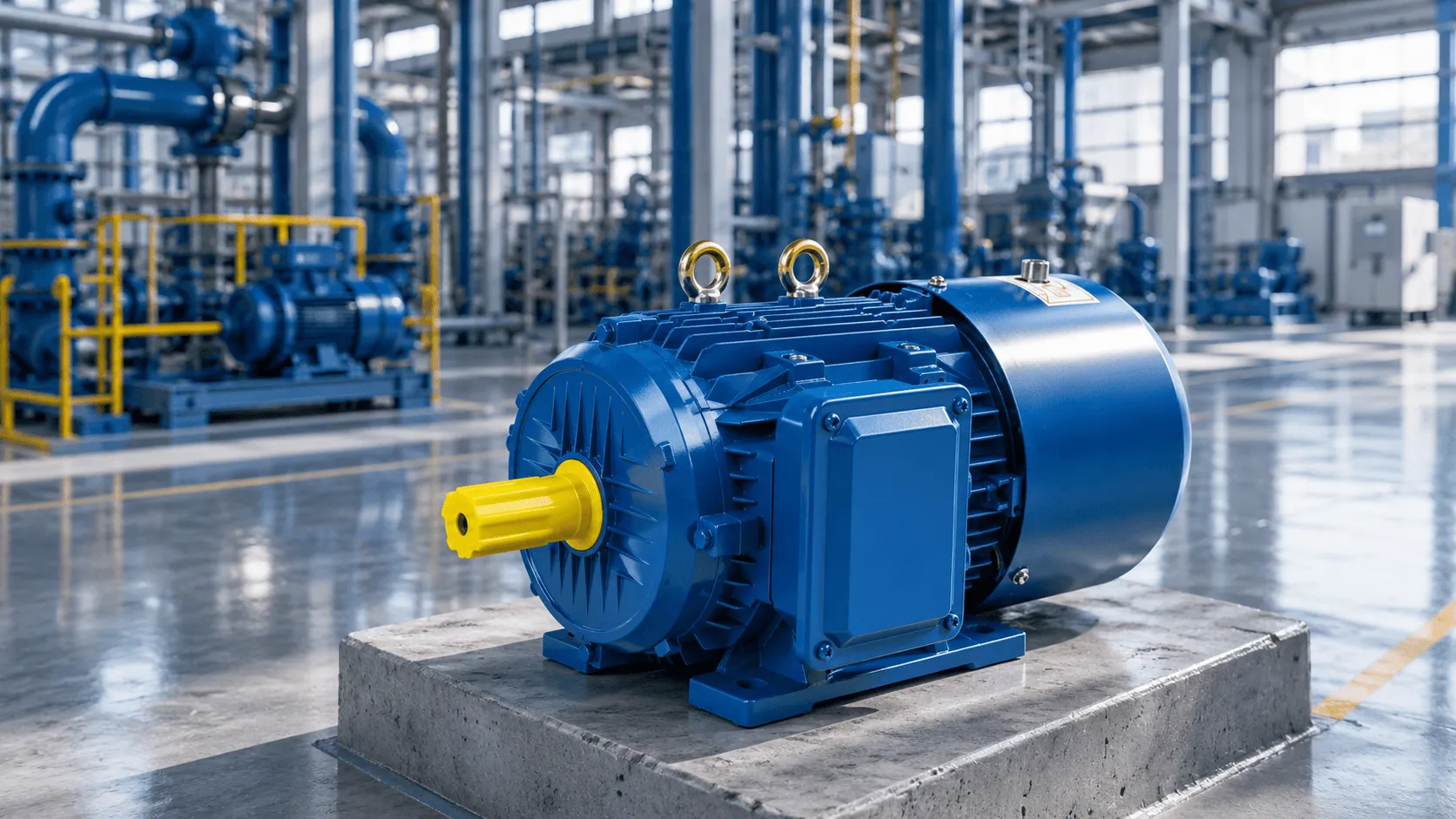
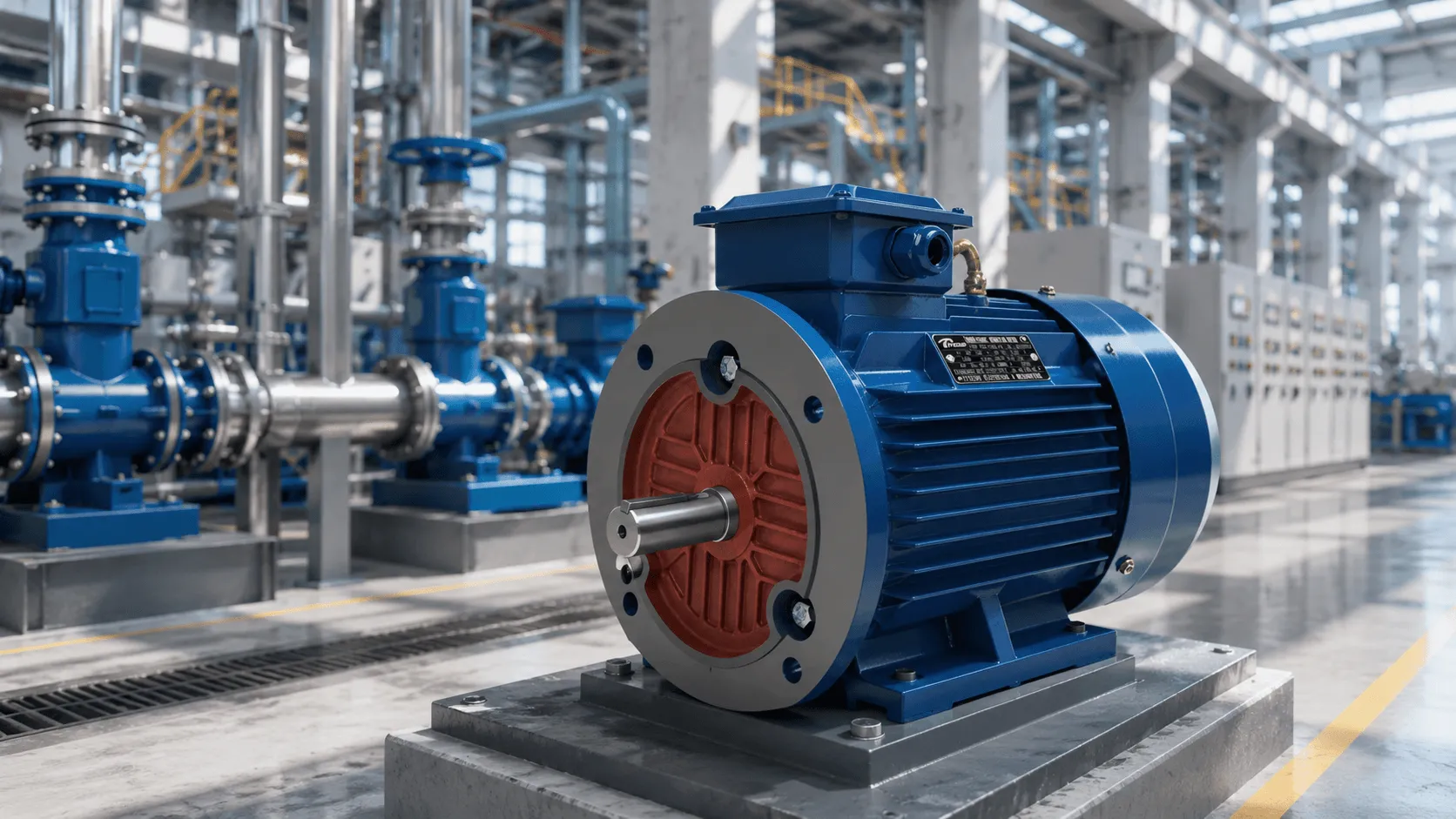
The YEJ series electromagnetic brake three-phase asynchronous motor is an integrated electromechanical system that combines a standard squirrel-cage induction motor with a DC electromagnetic disc brake assembly. Designed per IEC 60034 and JB/T6456 standards, these motors deliver instantaneous braking capability upon power loss, making them indispensable for applications demanding rapid stopping, precise positioning, and load-holding security.
Unlike conventional induction motors that rely on external mechanical brakes or regenerative braking systems, the YEJ series integrates the braking mechanism directly onto the motor’s non-drive end (NDE). This unified architecture eliminates coupling alignment issues, reduces installation footprint, and ensures synchronous braking response across the entire drivetrain.
2. Construction & Operating Principle
2.1 Structural Overview
The YEJ motor consists of two primary subsystems:
表格
| Component | Material / Specification | Function |
|---|---|---|
| Motor Housing | Die-cast aluminum (H63–H132) / Cast iron (H160–H280) | Structural rigidity, heat dissipation |
| Stator Core | Silicon steel DW470/DW600 (0.5 mm laminations) | Magnetic flux path, eddy current reduction |
| Rotor | Squirrel-cage aluminum die-cast | Electromechanical energy conversion |
| Winding Wire | QZ-2/155 or QZ-2/180 (Class F/H) | Thermal endurance, dielectric strength |
| Brake Coil | DC-excited electromagnetic winding | Generates braking force upon de-energization |
| Friction Disc | Composite friction material (non-asbestos) | Torque transmission during braking |
| Armature Plate | Steel with surface treatment | Magnetic attraction surface |
| Brake Spring | Alloy steel, pre-compressed | Applies mechanical braking force |
| Manual Release | Hand-lever mechanism | Emergency/manual brake disengagement |
2.2 Electromagnetic Braking Mechanism
The braking action operates on the fail-safe principle (power-off braking):
Energized State (Motor Running): When AC power is applied to the motor and the rectified DC voltage energizes the brake coil, the electromagnetic force Fem overcomes the spring force Fspring :
Fem=2μ0B2A>Fspring
Where:
- B = Magnetic flux density in the air gap (T)
- A = Pole face area (m²)
- μ0 = Permeability of free space (4π×10−7 H/m)
The armature plate is attracted toward the coil housing, compressing the brake spring and releasing the friction disc. The motor shaft rotates freely.
De-energized State (Braking): Upon power interruption, the electromagnetic field collapses exponentially:
B(t)=B0e−t/τ
Where the time constant τ=L/R (coil inductance / resistance). Once Fem<Fspring , the spring forces the armature plate against the friction disc, generating braking torque Tb :
Tb=n⋅μ⋅Fspring⋅reff
Where:
- n = Number of friction surfaces
- μ = Coefficient of friction (typically 0.35–0.45 for composite materials)
- reff = Effective friction radius (m)
3. Technical Specifications
3.1 Motor Electrical Parameters
2-Pole (3,000 r/min synchronous), 380V, 50Hz
表格
| Model | Power (kW) | Speed (r/min) | Efficiency (%) | Power Factor | Current (A) | Rated Torque (Nm) | Locked-Rotor Torque / Tn | Max Torque / Tn | Static Brake Torque (Nm) | No-Load Braking Time (s) |
|---|---|---|---|---|---|---|---|---|---|---|
| YEJ-801-2 | 0.75 | 2,825 | 75.0 | 0.84 | 1.8 | 2.54 | 2.2 | 2.3 | 7.5 | 0.10 |
| YEJ-802-2 | 1.1 | 2,825 | 77.0 | 0.86 | 2.5 | 3.72 | 2.2 | 2.3 | 7.5 | 0.10 |
| YEJ-90S-2 | 1.5 | 2,840 | 78.0 | 0.85 | 3.4 | 5.04 | 2.2 | 2.3 | 15 | 0.15 |
| YEJ-90L-2 | 2.2 | 2,840 | 80.5 | 0.86 | 4.8 | 7.40 | 2.2 | 2.3 | 15 | 0.15 |
| YEJ-100L-2 | 3 | 2,880 | 82.0 | 0.87 | 6.4 | 10.0 | 2.2 | 2.3 | 30 | 0.15 |
| YEJ-112M-2 | 4 | 2,890 | 85.5 | 0.87 | 8.2 | 13.2 | 2.2 | 2.3 | 40 | 0.15 |
| YEJ-132S1-2 | 5.5 | 2,900 | 85.5 | 0.88 | 11.1 | 18.1 | 2.0 | 2.3 | 80 | 0.15 |
| YEJ-132S2-2 | 7.5 | 2,900 | 86.2 | 0.88 | 15.0 | 24.7 | 2.0 | 2.3 | 80 | 0.15 |
| YEJ-160M1-2 | 11 | 2,930 | 87.2 | 0.88 | 21.8 | 35.9 | 2.0 | 2.3 | 150 | 0.30 |
| YEJ-160M2-2 | 15 | 2,930 | 88.2 | 0.88 | 29.4 | 48.9 | 2.0 | 2.2 | 150 | 0.30 |
| YEJ-160L-2 | 18.5 | 2,930 | 89.0 | 0.89 | 35.5 | 60.3 | 2.0 | 2.2 | 150 | 0.30 |
| YEJ-180M-2 | 22 | 2,940 | 89.0 | 0.89 | 42.2 | 71.5 | 2.0 | 2.2 | 200 | 0.30 |
| YEJ-200L1-2 | 30 | 2,950 | 90.0 | 0.89 | 56.9 | 97.1 | 2.0 | 2.2 | 300 | 0.45 |
| YEJ-200L2-2 | 37 | 2,950 | 90.5 | 0.89 | 69.8 | 119.8 | 2.0 | 2.2 | 300 | 0.45 |
| YEJ-225M-2 | 45 | 2,970 | 91.5 | 0.89 | 84.0 | 144.7 | 2.0 | 2.2 | 450 | 0.45 |
4-Pole (1,500 r/min synchronous), 380V, 50Hz
表格
| Model | Power (kW) | Speed (r/min) | Efficiency (%) | Power Factor | Current (A) | Rated Torque (Nm) | Locked-Rotor Torque / Tn | Max Torque / Tn | Static Brake Torque (Nm) | No-Load Braking Time (s) |
|---|---|---|---|---|---|---|---|---|---|---|
| YEJ-801-4 | 0.55 | 1,405 | 71.0 | 0.75 | 1.57 | 3.74 | 2.2 | 2.4 | 7.5 | 0.10 |
| YEJ-802-4 | 0.75 | 1,405 | 73.0 | 0.76 | 2.02 | 5.10 | 2.2 | 2.4 | 7.5 | 0.10 |
| YEJ-90S-4 | 1.1 | 1,445 | 75.0 | 0.77 | 2.82 | 7.27 | 2.2 | 2.3 | 15 | 0.15 |
| YEJ-90L-4 | 1.5 | 1,445 | 78.0 | 0.79 | 3.70 | 9.91 | 2.2 | 2.3 | 15 | 0.15 |
| YEJ-100L1-4 | 2.2 | 1,440 | 80.0 | 0.81 | 5.16 | 14.6 | 2.2 | 2.3 | 30 | 0.15 |
| YEJ-100L2-4 | 3 | 1,440 | 82.0 | 0.82 | 6.78 | 19.9 | 2.2 | 2.3 | 30 | 0.15 |
| YEJ-112M-4 | 4 | 1,440 | 84.0 | 0.82 | 8.82 | 26.5 | 2.2 | 2.3 | 40 | 0.15 |
| YEJ-132S1-4 | 5.5 | 1,440 | 85.0 | 0.83 | 11.7 | 36.5 | 2.2 | 2.3 | 80 | 0.15 |
| YEJ-132S2-4 | 7.5 | 1,440 | 87.0 | 0.84 | 15.6 | 49.7 | 2.2 | 2.3 | 80 | 0.15 |
| YEJ-160M1-4 | 11 | 1,450 | 88.0 | 0.85 | 21.3 | 72.5 | 2.2 | 2.2 | 150 | 0.30 |
| YEJ-160M2-4 | 15 | 1,450 | 89.0 | 0.85 | 30.1 | 98.8 | 2.2 | 2.2 | 150 | 0.30 |
| YEJ-180M-4 | 18.5 | 1,455 | 90.5 | 0.86 | 36.5 | 121.5 | 2.2 | 2.2 | 150 | 0.30 |
| YEJ-180L-4 | 22 | 1,455 | 91.0 | 0.86 | 43.1 | 144.4 | 2.0 | 2.2 | 200 | 0.30 |
6-Pole (1,000 r/min synchronous), 380V, 50Hz
表格
| Model | Power (kW) | Speed (r/min) | Efficiency (%) | Power Factor | Current (A) | Rated Torque (Nm) | Locked-Rotor Torque / Tn | Max Torque / Tn | Static Brake Torque (Nm) | No-Load Braking Time (s) |
|---|---|---|---|---|---|---|---|---|---|---|
| YEJ-90S-6 | 0.75 | 910 | 72.5 | 0.70 | 2.3 | 7.87 | 2.0 | 2.2 | 15 | 0.15 |
| YEJ-90L-6 | 1.1 | 910 | 73.5 | 0.72 | 3.2 | 11.5 | 2.0 | 2.2 | 15 | 0.15 |
| YEJ-100L-6 | 1.5 | 940 | 77.5 | 0.74 | 4.0 | 15.2 | 2.0 | 2.2 | 30 | 0.15 |
| YEJ-112M-6 | 2.2 | 960 | 80.5 | 0.74 | 5.6 | 21.9 | 2.0 | 2.1 | 40 | 0.15 |
| YEJ-132S-6 | 3 | 960 | 83.5 | 0.76 | 7.2 | 29.8 | 2.0 | 2.2 | 80 | 0.15 |
| YEJ-132M1-6 | 4 | 960 | 84.0 | 0.77 | 9.4 | 39.8 | 2.0 | 2.2 | 80 | 0.15 |
| YEJ-132M2-6 | 5.5 | 960 | 85.3 | 0.78 | 12.6 | 54.7 | 2.0 | 2.0 | 150 | 0.30 |
| YEJ-160M-6 | 7.5 | 970 | 86.0 | 0.78 | 17.0 | 73.8 | 2.0 | 2.1 | 150 | 0.30 |
| YEJ-160L-6 | 11 | 970 | 87.0 | 0.78 | 24.6 | 108.3 | 2.0 | 2.1 | 150 | 0.30 |
| YEJ-180L-6 | 15 | 970 | 89.5 | 0.81 | 31.4 | 147.6 | 1.8 | 2.0 | 200 | 0.30 |
| YEJ-200L1-6 | 18.5 | 980 | 89.8 | 0.83 | 37.7 | 180.3 | 1.8 | 2.0 | 300 | 0.45 |
| YEJ-200L2-6 | 22 | 980 | 90.2 | 0.86 | 44.6 | 214.4 | 1.8 | 2.0 | 300 | 0.45 |
| YEJ-225M-6 | 30 | 980 | 90.2 | 0.85 | 59.3 | 292.4 | 1.7 | 2.0 | 450 | 0.45 |
3.2 Brake Technical Parameters
表格
| Frame Size | Armature Stroke (mm) | No-Load Braking Time (s) | Static Braking Torque (Nm) | Excitation Voltage (V DC) | Excitation Power (W) |
|---|---|---|---|---|---|
| YEJ-63 | — | 0.10 | 3.5 | 99 | 35 |
| YEJ-71 | — | 0.10 | 4.0 | 99 | 40 |
| YEJ-80 | 1.0 | 0.20 | 7.5 | 99 | 50 |
| YEJ-90 | 1.0 | 0.20 | 15 | 99 | 60 |
| YEJ-100 | 1.0 | 0.20 | 30 | 99 | 80 |
| YEJ-112 | 1.0 | 0.25 | 40 | 170 | 110 |
| YEJ-132 | 1.2 | 0.25 | 75 | 170 | 130 |
| YEJ-160 | 1.2 | 0.35 | 150 | 170 | 150 |
| YEJ-180 | 1.2 | 0.35 | 200 | 170 | 150 |
| YEJ-200 | 1.5 | 0.45 | 300 | 170 | 200 |
| YEJ-225 | 1.5 | 0.45 | 450 | 170 | 200 |
3.3 Braking Performance Analysis
The braking time tb under load conditions depends on the moment of inertia J and the braking torque Tb :
tb=Tb−TloadJ⋅ω0
Where:
- J = Total moment of inertia (motor + load) (kg·m²)
- ω0 = Initial angular velocity (rad/s)
- Tload = Load torque during braking (Nm)
For no-load braking (where Tload≈0 ):
tb0=TbJmotor⋅ω0
The braking torque ratiokb is a critical selection parameter:
kb=TnTb×100%
表格
| Frame Size | Rated Torque Range (Nm) | Brake Torque (Nm) | kb Range (%) |
|---|---|---|---|
| YEJ-80 | 2.5–5.1 | 7.5 | 150–300 |
| YEJ-90 | 5.0–11.5 | 15 | 130–300 |
| YEJ-100 | 10.0–19.9 | 30 | 150–300 |
| YEJ-112 | 13.2–26.5 | 40 | 150–300 |
| YEJ-132 | 18.1–54.7 | 75 | 137–415 |
| YEJ-160 | 35.9–108.3 | 150 | 138–418 |
| YEJ-180 | 71.5–147.6 | 200 | 135–280 |
| YEJ-200 | 97.1–214.4 | 300 | 140–309 |
| YEJ-225 | 144.7–292.4 | 450 | 154–311 |
4. Model Nomenclature System
plain
YEJ □□□ □ - □ - □
│   │   │   │   └── Mounting code (B3/B5/B35/V1/etc.)
│   │   │   └────── Pole number (2/4/6/8)
│   │   └────────── Core length code (S/M/L/1/2)
│   └────────────── Frame size (center height in mm)
└────────────────── Series designation (Y + EJ = Electromagnetic Brake)Example: YEJ-132M2-4-B5
- YEJ: Electromagnetic brake motor series
- 132: Center height = 132 mm
- M2: Medium frame, second core length
- 4: 4-pole (1,500 r/min synchronous)
- B5: Flange mounting (large flange)
5. Standard Operating Conditions
表格
| Parameter | Specification |
|---|---|
| Rated Voltage | 380 V (3-phase), 50 Hz / 60 Hz on request |
| Power Range | 0.12 kW – 45 kW (0.16 HP – 60 HP) |
| Frame Size | H63 – H280 (IEC 60072) |
| Pole Number | 2, 4, 6, 8 poles |
| Protection Class | IP54 / IP55 / IP56 (IEC 60034-5) |
| Insulation Class | Class F (155°C) standard; Class H (180°C) optional |
| Cooling Method | IC411 (Totally Enclosed Fan-Cooled) |
| Duty Type | S1 (Continuous Duty); S3, S4 available on request |
| Connection | Star (Y) for ≤ 3 kW; Delta (Δ) for ≥ 4 kW |
| Ambient Temperature | -15°C to +40°C |
| Altitude | ≤ 1,000 m |
| Relative Humidity | ≤ 90% |
| Brake Rectifier | Built-in, AC220V→DC99V (≤3kW); AC380V→DC170V (≥4kW) |
6. Dimensional & Mounting Data
6.1 Foot-Mounted (B3) Dimensions
表格
| Frame | A | B | C | D | E | F | G | H | K | L |
|---|---|---|---|---|---|---|---|---|---|---|
| 63 | 100 | 80 | 40 | ⌀11 | 23 | 4 | 12.5 | 63 | ⌀7 | 270 |
| 71 | 112 | 90 | 45 | ⌀14 | 30 | 5 | 16 | 71 | ⌀7 | 315 |
| 80 | 125 | 100 | 50 | ⌀19 | 40 | 6 | 21.5 | 80 | ⌀10 | 340 |
| 90S | 140 | 100 | 56 | ⌀24 | 50 | 8 | 21 | 90 | ⌀10 | 400 |
| 90L | 140 | 125 | 56 | ⌀24 | 50 | 8 | 27 | 90 | ⌀10 | 400 |
| 100L | 160 | 140 | 63 | ⌀28 | 60 | 8 | 31 | 100 | ⌀12 | 440 |
| 112M | 190 | 140 | 70 | ⌀28 | 60 | 8 | 31 | 112 | ⌀12 | 480 |
| 132S | 216 | 140 | 89 | ⌀38 | 80 | 10 | 41 | 132 | ⌀12 | 567 |
| 132M | 216 | 178 | 89 | ⌀38 | 80 | 10 | 41 | 132 | ⌀12 | 567 |
| 160M | 254 | 210 | 108 | ⌀42 | 110 | 12 | 45 | 160 | ⌀14.5 | 700 |
| 160L | 254 | 254 | 108 | ⌀42 | 110 | 12 | 45 | 160 | ⌀14.5 | 780 |
| 180M | 279 | 241 | 121 | ⌀48 | 110 | 14 | 51.5 | 180 | ⌀14.5 | 880 |
| 180L | 279 | 279 | 121 | ⌀48 | 110 | 14 | 51.5 | 180 | ⌀14.5 | 880 |
Note: L dimension includes brake assembly overhang (typically +30–80 mm vs. standard Y-series). All dimensions in mm.
6.2 Flange-Mounted (B5) Dimensions
表格
| Frame | D | E | F | G | M | N | P | S | T | L |
|---|---|---|---|---|---|---|---|---|---|---|
| 63 | ⌀11 | 23 | 4 | 12.5 | 115 | 95 | 140 | 10 | 3.0 | 280 |
| 71 | ⌀14 | 30 | 5 | 16 | 130 | 110 | 160 | 10 | 3.0 | 315 |
| 80 | ⌀19 | 40 | 6 | 21.5 | 165 | 130 | 200 | 12 | 3.5 | 340 |
| 90S/L | ⌀24 | 50 | 8 | 27 | 165 | 130 | 200 | 12 | 3.5 | 400 |
| 100L | ⌀28 | 60 | 8 | 31 | 215 | 180 | 250 | 14.5 | 4 | 440 |
| 112M | ⌀28 | 60 | 8 | 31 | 215 | 180 | 250 | 14.5 | 4 | 480 |
| 132S/M | ⌀38 | 80 | 10 | 41 | 265 | 230 | 300 | 14.5 | 4 | 567 |
| 160M/L | ⌀42 | 110 | 12 | 45 | 300 | 250 | 350 | 18.5 | 5 | 780 |
| 180M/L | ⌀48 | 110 | 14 | 51.5 | 300 | 250 | 350 | 18.5 | 5 | 880 |
6.3 Mounting Configuration Availability
表格
| Mounting Code | Description | H63–H112 | H132–H160 | H180–H225 |
|---|---|---|---|---|
| B3 | Foot-mounted, horizontal | ✓ | ✓ | ✓ |
| B5 | Flange-mounted, large flange | ✓ | ✓ | ✓ |
| B14 | Flange-mounted, small flange | ✓ | ✓ | — |
| B35 | Foot + large flange | ✓ | ✓ | ✓ |
| B34 | Foot + small flange | ✓ | ✓ | — |
| V1 | Vertical, shaft downward | ✓ | ✓ | ✓ |
| V3 | Vertical, shaft upward | ✓ | ✓ | — |
| V5 | Wall-mounted, shaft left | ✓ | ✓ | — |
| V6 | Wall-mounted, shaft right | ✓ | ✓ | — |
| V15 | Vertical + flange, shaft down | ✓ | ✓ | — |
| V18 | Vertical + small flange | ✓ | — | — |
7. Application Engineering
7.1 Industry Deployment Matrix
表格
| Industry | Application | Critical Requirement | Recommended YEJ Spec |
|---|---|---|---|
| Machine Tools | CNC lathe spindle, milling head | Rapid stop for tool change | 4-pole, kb ≥ 150% |
| Material Handling | Overhead cranes, hoists | Load holding, anti-drop | 6-pole, kb ≥ 200% |
| Packaging | Carton sealers, palletizers | Precise indexing | 4-pole, braking time ≤ 0.2s |
| Textile | Warping machines, looms | Tension control, quick stop | 4-pole, Class F insulation |
| Printing | Offset presses, die-cutters | Registration accuracy | 4-pole, low backlash coupling |
| Food & Beverage | Conveyors, mixers | Hygienic design, washdown | IP55, aluminum housing |
| Construction | Hoists, winches, gates | Safety braking, outdoor duty | IP55, cast iron frame |
| Woodworking | Saws, planers, sanders | Emergency stop compliance | 2-pole, kb ≥ 200% |
| Automotive | Assembly line conveyors | High cycle rate | S3 duty, 60% CDF |
| Agriculture | Grain elevators, dryers | Dust protection | IP55, sealed bearings |
7.2 Braking Energy Dissipation
During each braking event, the kinetic energy of the rotating system is converted to heat at the friction interface:
Ebrake=21Jω02+21Iloadω02
The heat flux densityq at the friction surface:
q=Af⋅tbEbrake
Where Af = friction surface area (m²).
For high-cycle applications (S3 duty), the thermal capacity must be verified:
Qcycle=Ebrake⋅ncycles≤Qmax
Where ncycles = cycles per hour, Qmax = maximum permissible thermal load (manufacturer-specified).
7.3 Duty Cycle Derating
For S3 intermittent periodic duty, the equivalent thermal current is:
Ieq=Iratedtcycleton
Where:
- ton = operating time per cycle
- tcycle = total cycle time
- CDF (Cyclic Duration Factor) = ton/tcycle×100%
Standard CDF ratings: 15%, 25%, 40%, 60%
8. Comparative Analysis: YEJ vs. External Brake Systems
表格
| Evaluation Criteria | YEJ Integrated Brake | Motor + External Brake | Servo Motor + Drive |
|---|---|---|---|
| Installation Footprint | Compact (single unit) | Large (motor + brake + coupling) | Moderate |
| Shaft Alignment | Perfect (common shaft) | Requires precision alignment | Perfect |
| Braking Response Time | 0.10–0.45 s | 0.15–0.60 s (with coupling backlash) | < 0.05 s |
| Holding Torque | 130–400% Tn | Configurable | 100–300% Tn |
| Fail-Safe Operation | Yes (spring-applied) | Yes (if spring-applied type) | No (requires power) |
| Maintenance Points | 1 (integrated) | 3+ (motor, coupling, brake) | 2+ (motor, encoder) |
| Initial Cost | Low–Moderate | Moderate | High |
| Energy Consumption | Low (brake coil only) | Low | High (servo drive losses) |
| Positioning Accuracy | ±0.5–2° | ±0.5–2° | ±0.01° |
| Environmental Tolerance | High (no electronics) | High | Moderate (sensitive to EMI) |
| Best Application | General machinery braking | Very high torque requirements | Precision servo positioning |
9. Installation & Commissioning
9.1 Electrical Connection Diagram
plain
    L1 ──┬── U (Motor)
    L2 ──┼── V (Motor)
    L3 ──┼── W (Motor)
         │
         ├── Rectifier Module ──┬── +DC (Brake Coil)
         │    (AC→DC)           └── −DC (Brake Coil)
         │
    PE ──┴── Ground
Voltage Conversion:
- Motors ≤ 3 kW: AC 220V single-phase → DC 99V
- Motors ≥ 4 kW: AC 380V (derived from L1-L2) → DC 170V
9.2 Air Gap Adjustment
The brake air gap δ must be maintained within specification for proper operation:
表格
| Frame | Nominal Air Gap (mm) | Maximum Allowable (mm) | Adjustment Interval |
|---|---|---|---|
| YEJ-80 | 0.20 | 0.50 | 500,000 cycles |
| YEJ-90 | 0.20 | 0.50 | 500,000 cycles |
| YEJ-100 | 0.20 | 0.50 | 500,000 cycles |
| YEJ-112 | 0.25 | 0.60 | 500,000 cycles |
| YEJ-132 | 0.25 | 0.60 | 500,000 cycles |
| YEJ-160 | 0.35 | 0.80 | 1,000,000 cycles |
| YEJ-180 | 0.35 | 0.80 | 1,000,000 cycles |
| YEJ-200 | 0.45 | 1.00 | 1,000,000 cycles |
| YEJ-225 | 0.45 | 1.00 | 1,000,000 cycles |
9.3 Pre-Commissioning Checklist
表格
| Item | Check | Acceptance Criteria |
|---|---|---|
| 1 | Insulation resistance | ≥ 100 MΩ at 500V DC |
| 2 | Brake coil resistance | Within ±10% of nameplate value |
| 3 | Air gap measurement | Within nominal specification |
| 4 | Manual release function | Smooth operation, full release |
| 5 | Rotation direction | Clockwise when viewed from DE |
| 6 | No-load current | ≤ 40% of rated current |
| 7 | Braking time | Within catalog specification |
| 8 | Brake holding torque | ≥ rated static torque |
10. Maintenance & Troubleshooting
10.1 Preventive Maintenance Schedule
表格
| Interval | Component | Action | Indicator of Required Service |
|---|---|---|---|
| 250 hours | Brake air gap | Measure and record | Increased braking time |
| 1,000 hours | Friction disc | Visual inspection for wear | Brake torque reduction >10% |
| 2,000 hours | Brake spring | Load test | Uneven braking, noise |
| 5,000 hours | Bearings | Temperature check, vibration analysis | Temperature >80°C, vibration >4.5 mm/s |
| 10,000 hours | Friction disc | Replace (typical life) | Wear approaching rivet heads |
| 20,000 hours | Brake coil | Resistance test, insulation check | Resistance change >15% |
| Annually | Rectifier | Output voltage verification | DC voltage < 90% nominal |
| Annually | Full assembly | Comprehensive inspection | Any abnormal operational symptom |
10.2 Common Faults & Remedies
表格
| Symptom | Probable Cause | Corrective Action |
|---|---|---|
| Motor runs, brake remains engaged | Rectifier failure; coil open circuit | Test rectifier output; measure coil resistance |
| Excessive braking time | Worn friction disc; excessive air gap | Replace friction disc; adjust air gap |
| Brake noise during engagement | Contaminated friction surface; uneven wear | Clean with solvent; replace disc if uneven |
| Brake slips under load | Glazed friction surface; insufficient spring force | Resurface or replace disc; test spring force |
| Brake coil overheating | Incorrect voltage; continuous energization | Verify rectifier output; check duty cycle |
| Vibration during braking | Misalignment; worn bearings | Check coupling alignment; replace bearings |
| Intermittent brake release | Loose connections; failing rectifier | Tighten terminals; replace rectifier module |
11. Quality Assurance & Certifications
表格
| Certification | Standard | Applicability |
|---|---|---|
| CE Marking | EU Machinery Directive 2006/42/EC | European market compliance |
| CCC | GB 18613 / GB 30253 | China Compulsory Product Certification |
| ISO 9001 | ISO 9001:2015 | Quality management system |
| IEC | IEC 60034-1, IEC 60034-5, IEC 60034-30 | International electrotechnical standards |
| EAC | TR CU 004/2011, TR CU 020/2011 | Eurasian Customs Union |
| UL/cUL | UL 1004 | North American market (optional) |
12. Selection Methodology
12.1 Step-by-Step Sizing Procedure
Step 1: Determine Load Requirements
- Calculate load torque: Tload=ωshaftPload
- Determine required braking torque: Tbrake≥1.5×Tload
- Assess duty cycle and cycles per hour
Step 2: Select Motor Power
- Required motor power: Pmotor=9550×ηdriveTload×n
- Apply service factor (typically 1.15–1.25 for brake motors)
Step 3: Verify Braking Performance
- Check braking torque ratio kb≥150%
- Verify braking time meets process requirements
- Confirm thermal capacity for cyclic duty
Step 4: Confirm Environmental Compatibility
- Ambient temperature range
- Protection class (IP rating)
- Hazardous area classification (if applicable)
12.2 Application Example
Application: 5 kW overhead crane hoist
- Load torque: 48 Nm at 1,440 r/min
- Required braking torque: 48×1.5=72 Nm
- Duty: S3, 40% CDF, 120 cycles/hour
Selection: YEJ-132S2-4
- Rated power: 7.5 kW (service factor = 1.5)
- Rated torque: 49.7 Nm
- Brake torque: 80 Nm (kb=161% )
- Braking time: 0.15 s (no-load)
- Estimated loaded braking time:
tb=80−48(0.08+Jload)×151≈0.35 s
This meets typical hoist requirements (≤ 0.5 s).
13. Conclusion
The YEJ series electromagnetic brake three-phase asynchronous motor represents a mature, cost-effective solution for applications requiring integrated braking capability. By combining a robust induction motor with a fail-safe DC electromagnetic brake in a single, compact package, the YEJ series eliminates the complexity, alignment challenges, and maintenance burden associated with external braking systems.
Key advantages for system designers and procurement professionals include:
- Fail-safe operation: Spring-applied braking ensures load holding during power failures
- Simplified mechanics: Single-shaft design eliminates coupling backlash and alignment issues
- Rapid response: Braking times from 0.10 to 0.45 seconds depending on frame size
- High torque margin: Static braking torque ranging from 130% to 400% of rated motor torque
- Broad applicability: Frame sizes from H63 to H280, power range 0.12–45 kW
- Low total cost of ownership: Minimal maintenance, long friction disc life, integrated rectifier
For applications in material handling, machine tools, packaging, and general industrial machinery where safety, reliability, and rapid stopping are non-negotiable, the YEJ series delivers proven performance at a fraction of the cost of servo-based alternatives.
All technical data conforms to IEC 60034 series standards and JB/T6456 industry specifications. For specialized applications involving high cycle rates, extreme environments, or precise positioning requirements, consult factory application engineering for customized solutions.
No comments yet